Dismantaling Joints
GENERAL
Dismantling Joints play a decisive role in the design and layout of pipelines and valves. They are an essential aid during the installation and removal of pipe sections and valves. Without a dismantling joint offering longitudinal adjustment, it is almost impossible to insert a valve exactly into a pipe section.
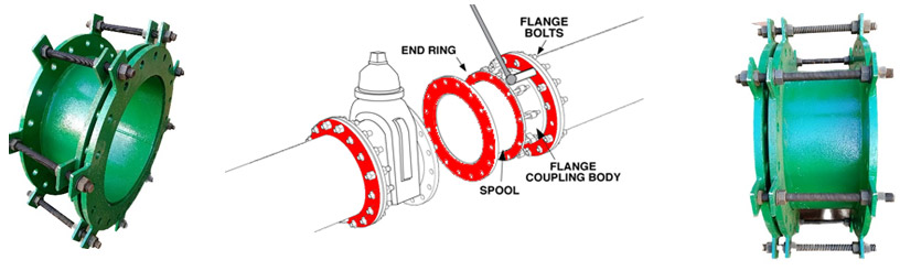
Thanks to this adjustability of the dismantling joint, the valve can be fitted next to the dismantling joint, and the dismantling joint can be to set to the exact length required prior to being securely connected to flanges.
The reverse sequence is used for dismantling, where readjustment of the length of the dismantling joint creates enough space to loosen and remove the valve. In both cases, the dismantling joint guarantees fast installation and removal, thus contributing to increased efficiency and reducing site operations and down time. The procedure is similar where pipe sections have to be fitted together. Certain types of dismantling joints are also suitable for use without restraint in flexible pipelines. Finally, dismantling joints can be used to fill gaps e.g. where a pump installed in a fixed position has to be connected to a pipe protruding from a wall.

MOC
Carbon Steel
Stainless Steel
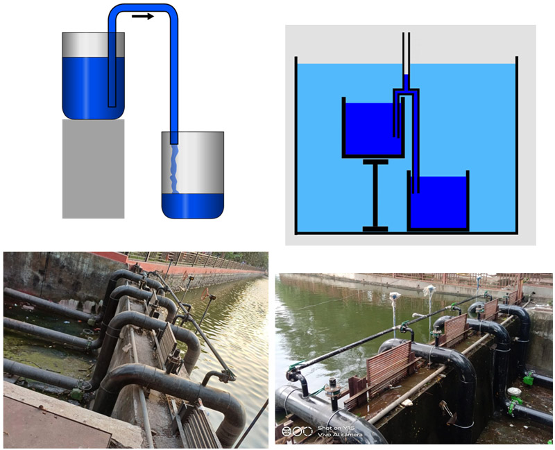
Siphon System
GENERAL
A siphon is a tube that allows liquid to travel upward, above the surface of the origin reservoir, then downwards to a lower level without using a pump but powered by the fall of the liquid as it flows down the tube under the pull of gravity, then discharging at a level lower than the surface of the reservoir from which it came. When a certain amount of water moves over the bend in the siphon, gravity pulls it down on the longer leg lowers the atmospheric pressure in the bend of the siphon.
There are two leading theories about how siphons cause liquid to flow uphill, against gravity, without being pumped, and powered only by gravity. The traditional theory for centuries was that gravity pulling the liquid down on the exit side of the siphon resulted in reduced pressure at the top of the siphon. Then atmospheric pressure was able to push the liquid from the upper reservoir, up into the reduced pressure at the top of the siphon, like in a barometer or drinking straw, and then over. However, it has been demonstrated that siphons can operate in a vacuum and to heights exceeding the barometric height of the liquid. Consequently, the cohesion tension theory of siphon operation has been advocated, where the liquid is pulled over the siphon in a way similar to the chain fountain. It need not be one theory or the other that is correct, but rather both theories may be correct in different circumstances of ambient pressure. The atmospheric pressure with gravity theory cannot explain siphons in vacuum, where there is no significant atmospheric pressure.
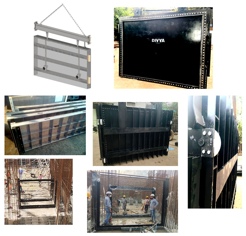
Stop Log Gates
GENERAL
Stoplogs Gates are hydraulic engineering control elements that are used in floodgates to adjust the water level or discharge in a river, canal, or reservoir.. Stoplogs are typically long rectangular beams or boards that are placed on top of each other and dropped into premade slots inside a weir, gate, or channel. Present day, the process of adding and removing stoplogs Gates is not manual, but done with hydraulic stoplog lifters and hoists. Since the height of the barrier can only be adjusted through the addition and removal of stoplogs Gates, finding a lighter and stronger material other than wood or concrete became a more desirable choice Other materials, including steel and composites, can be used in stoplogs Gates as well. Stop log Gates are designed to cut off or stop flow through a conduit.
MOC Of VESSEL
SA 516 Gr.60/70
IS 2062 E-250
As per client Req.
MAIN FEATURES
- Application : Raw Water, Pure Water, Sewage Water.
- Assembly: Single Piece / Multiple pieces
- Manual / Mechanized lifting arrangement
- Sealing : EPDM Rubber, Neoprene, Polyurethane
- Single Piece Size Max. (WxH) = 3.9 x 3.5Mtr
- Replaceable Seals
MOC
- Stainless Steen
- Duplex Stainless steel
- Mild Steel
- Galvanized Steel
- FRP
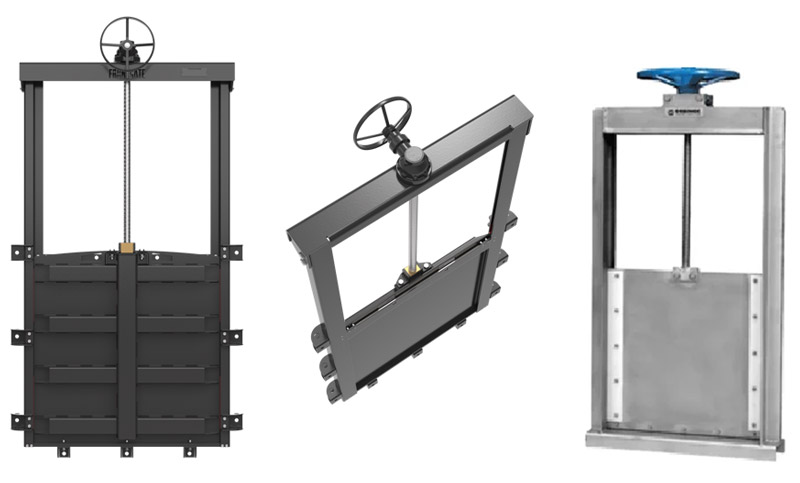
Fabricated Sluice gate
GENERAL
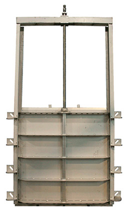
Sluice Gates is a fabricated rectangular Sliding Gates which Slide in Fixed Guide Frames and Itsused for Stop the Water passage in rivers Barrage, Small Pump houses, Dams outlet, etc. Sluice Gate is stop the water passage with its upward and downward motion using with its Spindle Type arrangement which is operated on top by manually as well as electrically with the help of Electrical Actuators.In Sluice Gates Water passage is block due to sealing method using of Rubber seal on its, Generally this seals are Made up using Natural rubber ,EPDM Rubber ,Neoprene Rubber .Sluice Gates are Lighter in Weight than Stop Log gates and also operate manually .
MAIN FEATURES
- Application : Raw Water, Pure Water, Sewage Water.
- Assembly: Single Piece
- Manual / Electrical
- Sealing : EPDM Rubber, Neoprene
- Single Piece Size Max. (WxH) = 2 x 2Mtr
- Replaceable Seals
MOC
- Stainless Steen
- Duplex Stainless steel
- Mild Steel
- Galvanized Steel
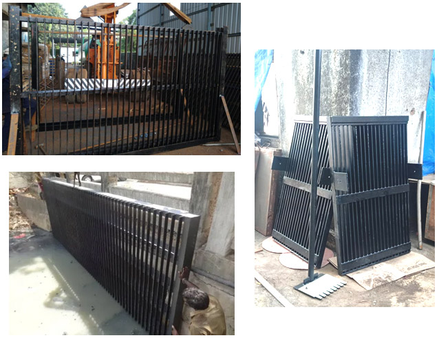
Trash Rack and Cource Screens
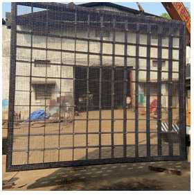
GENERAL
Trash Rack screens with vertical flat bars or Wire Mesh spaced apart is used to prevent large floating wastes or Debris from travelling further into intake structure, pumping station and treatment plants. The screen is provided either with rollers for smooth movement Or Without rollers. Sometimes trash rack screens are also used as fixed type screens with manual cleaning arrangement In movable screens it have motorized operation to raise or lower the screen. The cleaning of screen has to be done manually after raising the screen up to operating platform.
TYPE OF SCREENS
Manual Bar screens
Wire mesh screens
MOC
Carbon Steel
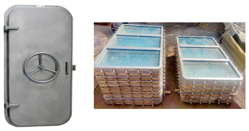
Water Tight Windows and Doors
GENERAL
This Doors and window is widely used in commercial ships, others and Under Water Jetties to provide protection against severe winds and Water. Also,clients can avail the offered Marine Water tightness. Water tightness is a feature that can never be missing on board of any boat. Watertight doors and Window are special types of doors found on ships that prevent the ingress of water from one compartment to another during flooding or accidents and therefore act as a safety barrier.
It limits the spread of water inside the vessel. These doors are used onboard in many ships such as in the fore and aft passageways underdeck and in engine room bulkheads leading to shaft tunnels in container vessels, large passenger ships, offshore vessels, oil exploration vessels.
They are used in areas where chances of flooding are high. Areas such as engine room compartments and shaft tunnels and some of such places.
Therefore it is important that crew members are familiar with the system as well as the location of different powered watertight doors aboard ship.
To make it simpler, a watertight door can prevent the passage of water in both directions when subjected to a head of water i.e it can withstand water pressure from both sides. They are designed to withstand continuous submersion and are therefore located below waterline like shaft tunnels, ballast tanks, bow thruster compartments etc. all openings below the waterline has to be watertight.
Water tight doors, on the other hand, is designed to withstand brief submersion. They are located above the waterline and can withstand the weather condition as found offshore which means from the outside.
MAIN FEATURES
- Application : Sea Water.
- Assembly: Single Piece
- Manual operation
- Sealing : EPDM Rubber, Neoprene
- Replaceable Seals
MOC
- Stainless Steen
- Duplex Stainless steel
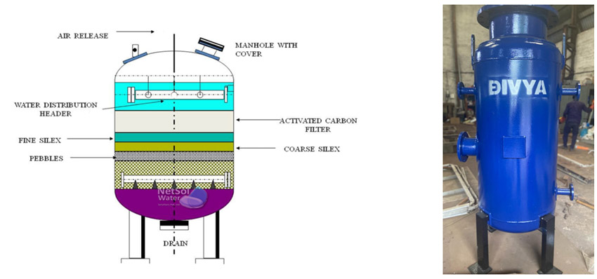
Sand Filter
GENERAL
Sand filters are used as a step in the water treatment process of water purification.
There are three main types; rapid (gravity) sand filters, upward flow sand filters and slow sand filters. All three methods are used extensively in the water industry throughout the world. The first two require the use of flocculants chemicals to work effectively while slow sand filters can produce very high quality water with pathogens removal from 90% to >99% (depending on the strains), taste and odour without the need for chemical aids. Sand filters can, apart from being used in water treatment plants, be used for water purification in singular households as they use materials which are available for most people.
Overall, there are several categories of sand bed filter:
- rapid (gravity) sand filters
- rapid (pressure) sand bed filters
- up flow sand filters
- slow sand filters